Interaction of Light and Materials
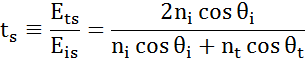
Maxwell’s equations must remain satisfied when light interacts with a material, which leads to boundary conditions at the interface. Incident light will reflect and refract at the interface, as shown in the figure below. The angle between the incident ray and sample normal (θi) will be equal to the reflected angle, (θr). Light entering the material is refracted at an angle θt given by:
![]()
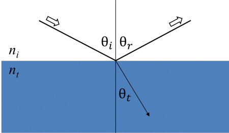
Light reflects and refracts according to Snell’s law.
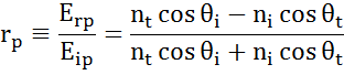
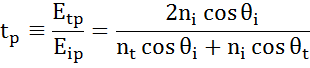
The same occurs at each interface where a portion of light reflects and the remainder transmits at the refracted angle. The boundary conditions provide different solutions for electric fields parallel and perpendicular to the sample surface. Therefore, light can be separated into orthogonal components with relation to the plane of incidence. Electric fields parallel and perpendicular to the plane of incidence are considered p- and s- polarized, respectively. These two components are independent and can be calculated separately. Fresnel described the amount of light reflected and transmitted at an interface between materials:
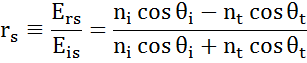
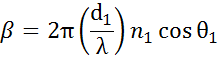
Thin film and multilayer structures involve multiple interfaces, with Fresnel reflection and transmission coefficients applicable at each. It is important to track the relative phase of each light component to determine correctly the overall reflected or transmitted beam. For this purpose, we define the film phase thickness as:
The superposition of multiple light waves introduces interference that depends on the relative phase of each light wave. The figure below illustrates the combination of light waves in the reflected beam and their corresponding Fresnel calculations.
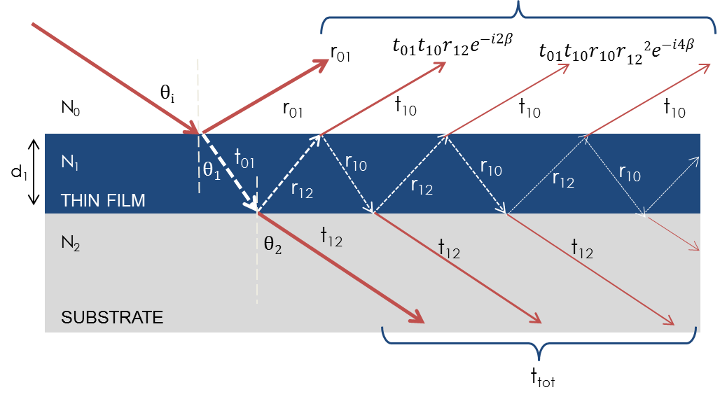
Light reflects and refracts at each interface, which leads to multiple beams in a thin film. Interference between beams depends on relative phase and amplitude of the electric fields. Fresnel refection and transmission coefficients can be used to calculate the response from each contributing beam.