What does an ellipsometer measure?
Answer:
Ellipsometry uses polarized light to characterize thin film and bulk materials. The light undergoes a change in polarization as it interacts with the sample structure. The measurement is typically expressed as two values: Psi (Ψ) and Delta (∆). The data are then analyzed to determine material properties of interest.
What are Ψ and ∆?
Answer:
Psi and Delta represent the raw measurement from an ellipsometer. They describe the change in polarization that occurs when the measurement beam interacts with a sample surface. The incident light beam contains electric fields both parallel (p-) and perpendicular (s-) to the plane of incidence.
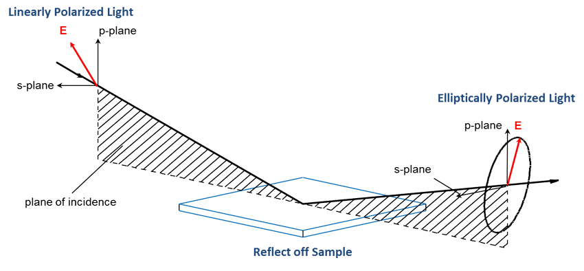
The surface differentiates between the p– and s– light, causing a change in the outgoing polarization. This is represented by both an amplitude ratio (tanΨ) and phase difference (∆):
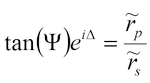
where Rp and Rs are the Fresnel reflection coefficients for the p– and s– polarized light, respectively.
Why is data analysis necessary for ellipsometry measurements?
Answer:
Ellipsometry measures two values, Ψ and ∆, which are related to the polarization change in the light that interacts with a sample. By themselves, Ψ and ∆ aren’t very informative. We really want to determine film thickness, optical constants, refractive index, surface roughness, and other physical properties of the sample. These properties are found by using the measured values (Ψ and ∆) in various equations and algorithms to produce a model that describes the interaction of light with the sample.
For more detailed information see Data Analysis or Ellipsometry Measurements.
Why is it important to measure at multiple wavelengths?
Answer:
There are multiple advantages to spectroscopic ellipsometry measurements, including a) Provides a unique answer, b) Improved sensitivity to material properties, and c) Data at wavelengths of interest for a desired application.
A. Provides a Unique Answer.
One of the easiest ways to improve the performance of an ellipsometer is to increase the number and range of measured wavelengths. Each new wavelength contains information about the sample properties. In the early days of ellipsometry, a laser was used to collect data at a single wavelength. With two measured values (Ψ and ∆), only two unknown sample properties could be determined. Even in a simple case, film thickness and refractive index could not be uniquely determined from a single layer film on known substrate. Incorrect results would occur if the film was absorbing, graded, or rough. Even for the ideal case of a perfect transparent film, the cyclic nature of single-wavelength ellipsometry measurements produce multiple answers, as shown in Figure below. The possible thicknesses are separated by the thickness period and an educated guess is required to fall into the correct solution.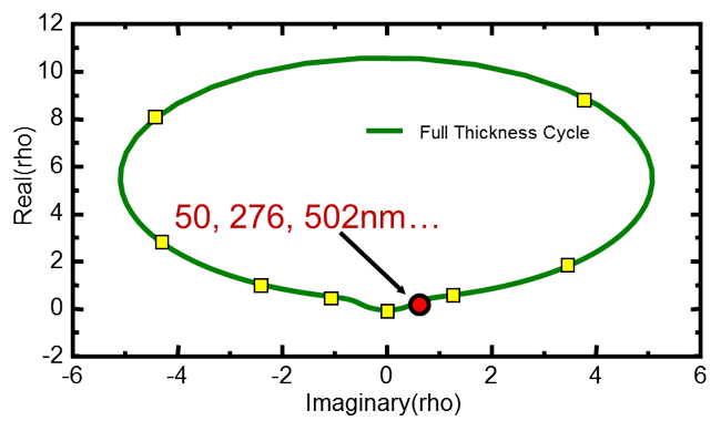
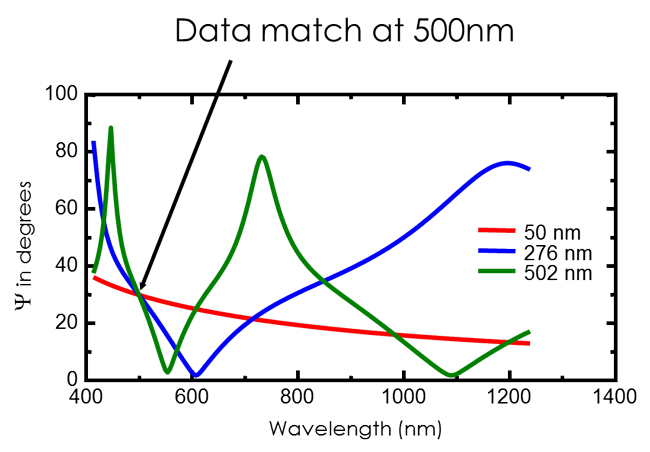
For this case, spectroscopic ellipsometry over-determines the film thickness. While the index of refraction will be wavelength dependent, the thickness remains the same. Thus, 100 wavelengths produce 200 data (Ψ,∆ X 100) with only 101 unknowns. The spectroscopic measurement quickly removes the “periodicity” problem by eliminating all except the correct answer. This is demonstrated for the first three possible solutions to the single-wavelength cycle from above. Note that while the data are identical at the single-wavelength of 500nm, the spectral response is entirely unique.
B. Improved Sensitivity to Material Properties.
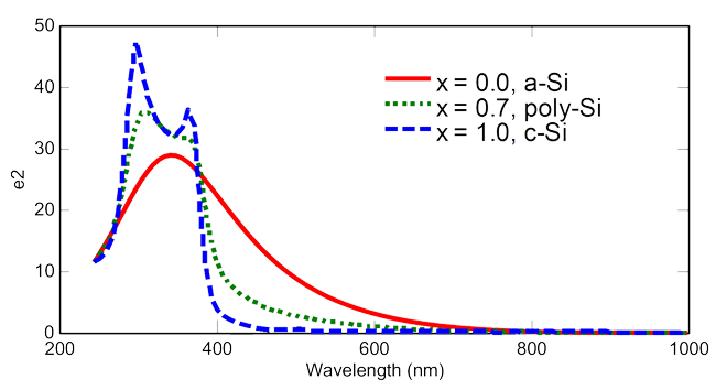
A specific wavelength range is often required to measure special material properties. For example, the conductivity of transparent conductive oxide (TCO) films will appear as a strong absorption in the infrared and tail into the near infrared. Visible wavelengths will not be able to measure the conductivity of the TCO, but would be required to determine film thickness. Molecular bonding information will only be available at mid-infrared wavelengths, where the slower frequency is able to vibrate the atoms in a material. The ultraviolet spectrum is often the focus of electronic transitions, which hold information about the structure of a material. For example, the UV absorption shape of silicon films is used to determine the layer crystallinity. If the film is amorphous, the absorption is broadened with no critical point features. As crystallinity increases, the absorption features in the ultraviolet become more distinct. This is shown in the graph below.
With SE systems that feature a broad spectral coverage, you get the simultaneous benefits from all wavelengths. This is why the trend with SE systems is to offer more wavelengths over a wider spectral range.
C. Results at Wavelengths of Interest for a Desired Application.
For many applications, optical properties are desired at specific wavelengths. For example, the semiconductor industry is interested in lithography which requires ellipsometry measurements in the UV region (157nm, 193nm, 248nm,…). The display industry is interested in the visible spectrum. Optical coatings require measurement at their design wavelengths, whether at visible, near infrared or even mid-infrared wavelengths. Woollam spectroscopic ellipsometers cover the spectral range from 33 microns to 140nm. This range offers an incredible flexibility that can meet almost any application requirement.
How does spectroscopic ellipsometry (SE) determine film thickness?
Answer:
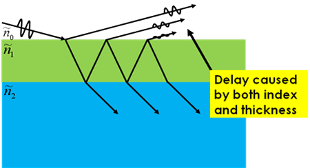
Spectroscopic ellipsometry is very sensitive to the film thickness. As the film thickness increases, there is an increasing separation between the light reflected from the surface and the light that travels through the film, as shown below. This causes a phase delay that is related to both the physical thickness and the index of refraction. Thus, spectroscopic ellipsometry measurements contain the information to accurately measure both thickness and index.
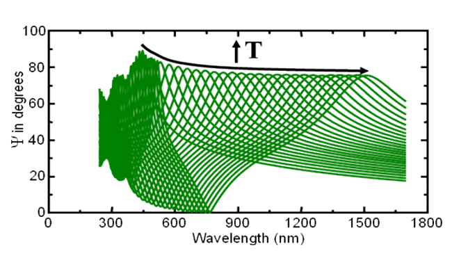
Spectroscopic ellipsometry data provide information about the thickness based on the position and number of interference oscillations. The graph below shows the Psi curve for a series of thin SiO2 films of different thicknesses. As the thickness (T) increases, the interference oscillations shift toward longer wavelengths.
What is the minimum film thickness spectroscopic ellipsometry can determine?
Answer:
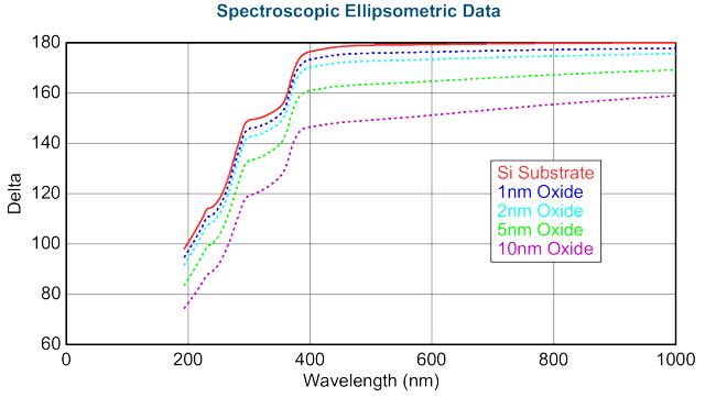
Spectroscopic ellipsometry is very sensitive to the presence of surface layers on the order of just a fraction of a nanometer. Sensitivity primarily comes from changes in phase (Delta), as is shown in the graph below for a series of thin oxides on silicon substrate. However, the interaction of light and these ultra-thin layers does not provide adequate sensitivity to simultaneously determine both thickness and refractive index. For this case, it is safest to assume an approximate refractive index (often measured from a thicker film) and then only determine the film thickness. In a few cases, ultra-thin films have been characterized to determine both thickness and refractive index simultaneously1.
1H. Arwin and D.E. Aspnes “Unambiguous Determination of Thickness and Dielectric Function of Thin Films by Spectroscopic Ellipsometry”, Thin Solid Films, 113 (1984) 101.
What is the maximum thickness spectroscopic ellipsometry can determine?
Answer:
The upper thickness limit for spectroscopic ellipsometry measurements depends on the measurement wavelengths. As the film becomes thicker, the large number of data oscillations becomes difficult to resolve at shorter wavelengths. The oscillations are better separated at longer wavelengths. Thus, it is common to use near infrared or even mid-infrared measurements to measure films up to 50 microns thick. However, these layers are beyond the typical range for SE measurements, and film uniformity becomes much more important. The preferred limit for most visible-to-near infrared measurements is less than 5 microns. Even for films that are 1 to 5 microns thick, it is best to measure with multiple angles of incidence to gain confidence that you have a unique thickness solution.
How does spectroscopic ellipsometry determine refractive index?
Answer:
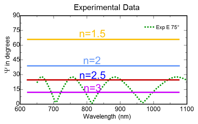
In addition to thickness information, the shape of the data oscillations is dependent on the film index of refraction. The figure below shows oscillations in Psi that have a specific amplitude. The amplitude of the oscillations determines the correct refractive index of the film. This is demonstrated by showing different amplitudes for a series of refractive index values.
What type of coatings can spectroscopic ellipsometry measure?
Answer:
Ellipsometry is used to measure a wide variety of thin films. There is no restriction on the type of material, provided that light reflects from the surface. If the coating is too rough, it scatters the probe beam away from the detector, which prevents spectroscopic ellipsometry measurements. It is very common to apply spectroscopic ellipsometry to dielectrics, organics, semiconductors, and even metal layers. The coatings can be isotropic or anisotropic, homogenous or graded. Spectroscopic ellipsometry can even be applied to multilayer structures, with films of different materials. The only constraint for thickness measurements is that light can pass through to the underlying substrate and back.
Can spectroscopic ellipsometry measure absorbing films?
Answer:
Spectroscopic ellipsometry has been used successfully for many different absorbing film applications. If thickness is desired, the absorbing film must be thin enough (typically < 50nm) to avoid complete absorption of the measurement beam before it can travel through the film. The number of unknowns for an absorbing film must also be considered. A good review of methods used to characterize absorbing films is given by Hilfiker et. Al. [/av_toggle] [av_toggle title='What are the benefits of spectroscopic ellipsometry measurements at variable angles of incidence (VASE)?' tags='' av_uid='av-58ns6'] Answer:
Ellipsometry measurements are typically performed at oblique angles near the Brewster angle. In the early days of ellipsometry, the Brewster angle was stressed because the ellipsometers took their best measurements at this position. This is much less important with modern ellipsometers that incorporate compensators (see FAQ #14), but the largest changes in polarization still occur at oblique angles. The typical range for spectroscopic ellipsometry measurements is 50° to 75°. Standard measurements of thickness and refractive index only require a single angle of incidence. As the sample complexity increases, the need for multiple angles of incidence increases. It is recommended to take 2 or 3 angles of incidence for very thick films (> 1 micron), index graded films, anisotropic materials, and complex multilayers. For samples that do not require multiple angles of incidence, extra angles provide a boost in confidence that your model is unique.
What is in situ spectroscopic ellipsometry?
Answer:
In situ is Latin for “in the place”. For ellipsometry, this means the measurements are taken while the sample is “in place” in a special chamber or cell. In situ ellipsometry requires that the ellipsometer is attached to the process chamber/cell or that the process chamber/cell is mounted on the ellipsometer base. The figure below shows an M-2000 spectroscopic ellipsometer system mounted to an ALD chamber, where the films are being deposited. In situ measurements of the surface can monitor the layer-by-layer growth. For further info see ‘Spectroscopic Ellipsometry for ALD Technology’.
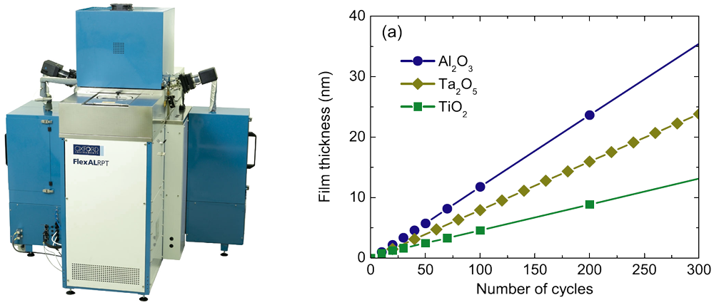
Thickness of the metal oxide films: Al2O3, Ta2O5 and TiO2 as a function of number of ALD cycles as determined from the in situ SE measurements.
Smaller process chambers and cells can be attached to the ellipsometer base to allow in situ measurements as the film is changing. A liquid cell, electrochemical cell, or QCM cell can easily be mounted on the system to monitor the liquid-solid interface as process variations occur. Heat stages or cryostats can also be mounted to monitor the sample temperature in situ.
E. Langereis, S.B.S. Heil, H.C.M. Knoops, W. Keuning, M.C.M. van de Sanden, W.M.M. Kessels, “In situ spectroscopic ellipsometry as a versatile tool for studying atomic layer deposition”, J. Phys. D: Appl. Phys., 42 (2009) 9.
How does spectroscopic ellipsometry compare to spectrophotometric measurements?
Answer:
Spectroscopic ellipsometry (SE) and Spectrophotometry (R/T) are both optical measurement techniques. While spectroscopic ellipsometry measures change in polarization, R/T measures intensity of reflected or transmitted light. The techniques are often complementary and can be combined to provide more information about absorbing thin films (Hilfiker et al.).
There are a few notable advantages to spectroscopic ellipsometry. First, spectroscopic ellipsometry gathers information about phase (∆), which is highly sensitive to very thin surface films (<10nm). Figure 1 shows the change in Reflectance caused by a thickness change of 0.1nm on a 10nm thick SiO2 layer on Si. A typical reflectometer system cannot accurately measure intensity values to better than 0.1%, and therefore reflectivity measurements are not sensitive to small changes in ultra thin film thickness. (Reflectance precision may be better than 0.1%, but data accuracy is needed for thickness accuracy.) The ellipsometric sensitivity to a similar change in thin film thickness is shown in Figure 2. Typical ellipsometers can accurately measure psi and delta to better than 0.02° and 0.1° respectively. Even film thickness changes down to the sub-Angstrom scale can be easily captured with this technique.
Reflectometer vs. Ellipsometer
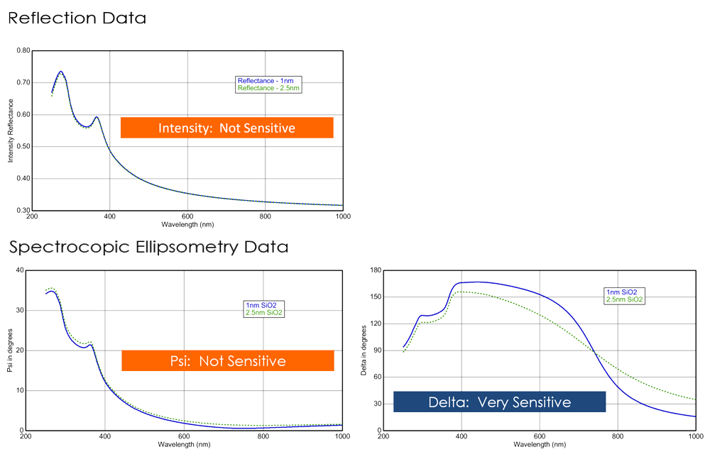
Thickness change of 0.1nm on a 10nm thick SiO2 layer on Si, notice the phase information gives ellipsometry much higher sensitivity to very thin films.
Second, ellipsometry measures the polarization state of light by measuring a ratio of values, rather than the absolute intensity. This allows spectroscopic ellipsometry measurements to be much more accurate with low or even fluctuating light intensities. Third, since Reflectance measures absolute intensity, it requires an “accurate” (calibrated) standard in order to be a quantitative measurement. The standard must be maintained to ensure accurate measurements over time.
Why do Woollam spectroscopic ellipsometry systems use compensators in their optical design?
Answer:
Every Woollam ellipsometer system includes a compensator to manipulate the polarization state. For the VASE and VUV-VASE, this involves our patented AutoRetarder before the sample. For the M-2000, alpha-SE, and IR-VASE we incorporate rotating compensator technology. There are many advantages to using compensators in an ellipsometer design, including:
- High accuracy on any sample.
- Measure full range of Psi (0 to 90°) and Delta (0° to 360°).
- Determine depolarization (see What is Depolarization?).
- Measure more elements of the Mueller-matrix (see What is the Mueller-matrix?).
AutoRetarder
The AutoRetarder is a computer controlled MgF2 Berek waveplate (compensator) used to accurately introduce retardance into the beam path. Because the compensator is under computer control, it is possible to generate appropriate retardance values (0 – 90°) over a broad (140 – 2500 nm) spectral range. The retardance is automatically adjusted to give the highest measurement accuracy for any sample.
Rotating Compensator
The Rotating Compensator Ellipsometer (RCE) configuration spins a compensator either before or after the sample to continuously adjust the retardance. This allows the measured SE data to be calculated from many simultaneous polarizations. A key advantage to this technology is its compatibility with CCD detection for parallel read-out of an entire spectrum in a fraction of a second. Not other technology can provide highly-accurate spectroscopic ellipsometry measurements at many hundreds of wavelengths in less than 1 second.
What is depolarization?
Answer:
Spectroscopic ellipsometry measurements determine the change in polarization for a light beam reflecting or transmitting from a surface. If the measurement system and sample are ideal, the incoming and detected light are both fully polarized. However, real-world measurement systems and samples can cause some of the light to become unpolarized. Depolarization describes the percentage of light that has become unpolarized.
Depolarization can be measured by ellipsometer systems that include a compensator. Thus, all Woollam ellipsometers can measure this additional information about the sample or measurement. Depolarization from the measurement system is classified as angular spread, bandwidth effects, or both. The samples can introduce depolarization if they are non-uniform or there are reflections from the backside.
Depolarization measurements are very useful to quantify the effects of non-ideal samples that may involve non-uniform thin films or patterned layers. Depolarization measurements are also useful when characterizing thin films on transparent substrates. If light reflects from the backside of the substrate, it returns to the detector and is incoherent with reflections from the top surface. This often results in depolarization of the measurement beam, which can be used to quantify the effects of backside reflections.
What is the Mueller-matrix?
Answer:
The Mueller-matrix completely specifies the interaction of light from a specular sample. Unlike the Jones-matrix, which can only represent polarized light, the Mueller-matrix can describe polarized, partially-polarized and even unpolarized light. The Mueller-matrix is a 4X4 matrix that describes the reflection or transmission of light, where incoming and outgoing light beams are described by their 4-element Stokes vectors.
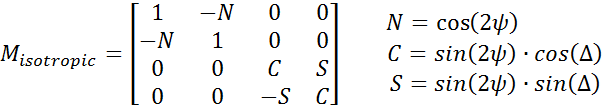
Any ellipsometer with a compensator (See Why do Woollam spectroscopic ellipsometry systems use compensators in their optical design?) can measure 12 of the 16 elements of the Mueller-matrix. If a compensator is placed before and after the sample, then it is possible to measure all 16 elements of the Mueller-matrix. However, there is plenty of redundancy in the Mueller-matrix that allows all common samples to be fully characterized without measuring the entire Mueller-matrix. The equation shown below shows the Mueller-matrix for an isotropic sample. If the measurement is entirely polarized, there are only two parameters that need to be measured: Psi and Delta. Even if the sample is depolarizing, there are only 3 elements of the Mueller-Matrix that need to be measured. For anisotropic-depolarizing samples, the number of independent parameters increases to seven. For more complex samples, the Mueller-matrix elements can be used to observe the cross-polarization and scattering effects which are induced by the sample, even though they can’t be modeled.
What factors should I consider when choosing a spectroscopic ellipsometer?
Answer:
The best way to decide which ellipsometer meets your requirements is to talk with an expert. You can call the Woollam Company and ask to speak with an Applications Engineer (+1-402-477-7501) or e-mail measurements@jawoollam.com and you will contact an engineer that has used every different type of ellipsometer to measure a wide variety of samples. You can also ask the Applications Engineer to send you a list of “power” users. These are reference customers that have been using a specific type of ellipsometer to do their research over the years and they are happy to talk about their ellipsometry experience.
When comparing the different ellipsometers available, you will want to consider:
Wavelength range…both the number and range of wavelengths that can be measured are important factors for how well an ellipsometer can solve thin film measurement problems.
Angle range…most samples can be measured with a single angle of incidence. Discuss with our engineers to see if your samples will require more angles – desirable for multilayers, anisotropic materials, and complex structures.
Measurement Speed…this can be an important factor if you are measuring in situ (see FAQ #12) or want to measure multiple points on a sample (uniformity mapping). While almost all ellipsometers can collect data in a fraction of a second, the basic technology involved may only allow high speed at a single wavelength (or limited number of wavelengths). For real-time spectroscopic measurements, you will need CCD detection, such as with our M-2000 instruments.
Accuracy…the measurement precision and accuracy for most ellipsometers far exceeds the typical need of users. For example, the precision of gate oxide measurements is often 0.003nm or better.
Technology…the technology used in an ellipsometer is often not of direct importance – but this technology leads to the characteristics we have already listed such as wavelength range, speed, and accuracy.
Features…you may want to consider the different needs for you application and whether the ellipsometer can be upgraded at a later time to meet future needs. Typical accessories include sample translation for uniformity mapping, liquid cells, temperature stages, focused spot, and even wavelength range expansions.
Price…there is a very wide price range for ellipsometer systems. Simple and high-end configurations exist to meet most budgets.
Why should I choose a Woollam spectroscopic ellipsometry system?
Answer:
From its beginning, the J.A. Woollam Company has dedicated itself solely to the development and refinement of spectroscopic ellipsometry. The J.A. Woollam Company was founded in 1987 in response to commercial demand for ellipsometry technology, which had been studied for decades at the University of Nebraska at Lincoln. Our efforts have led to over 100 patents and numerous awards.
Over half of J.A. Woollam employees are scientists and engineers dedicated to the advancement of this single technology. The J.A. Woollam Company possesses a level of expertise in spectroscopic ellipsometry that no other company can match. Our applications engineers have seen almost every ellipsometry application imaginable. This, combined with our versatile product line, allows the J.A. Woollam Company to provide excellent customer support for any application.
Our ellipsometry analysis software can tackle the most complex analysis while maintaining the ease of use necessary for industrial applications. J.A. Woollam has worked hard to provide the best product available with an excellent level of support.